High-angle reverse faults – the “fault-valve” model
Introduction and overall structure of valve model faults
A large number of mesothermal gold quartz deposits throughout the world have formed along high-angle reverse faults in tectonic shortening regimes (Fig. 1) (Faleiros et al., 2014; Sibson, 1988; Sibson 2004). These unfavourably oriented faults are inferred to periodically slip as a result of a build-up of fluid pressure. During slip a high volume of fluid is release giving rise to the process known as fault-valve rupture (Sibson, 1988). The following page discusses how fault-valve systems and associated mineralisation develops.
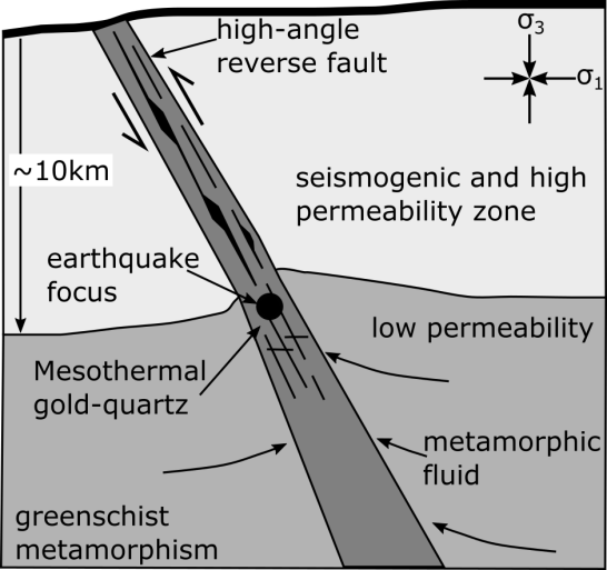
Figure 1. Schematic diagram of a high-angle reverse fault upon which fault-vale rupture is common. Figure modified from Sibson (1988).
Glossary
• Mesothermal: a class of hydrothermal mineral deposits originating in the Earth’s interior by deposition of a mineral mass from hot mineralized aqueous solutions, circulating at depths of approximately 1,000 m; the solutions are under great pressure and have temperatures of 200-300°C.
• Tectonic shortening: tectonic processes associated with the shortening and thickening of the crust or lithosphere.
• Seismogenic zone: the range of depths within the crust or lithosphere over which most earthquakes are initiated.
• Transpressional fault: strike-slip fault with a component of shortening.
• Lithostatic pressure: is the pressure or stress imposed on a layer of soil or rock by the weight of overlying material.
• Hydrostatic fluid pressure: the pressure exerted by a fluid at equilibrium at a given point within the fluid, due to the force of gravity.
• Suprahyrostatic fluid pressure: pressure greater than that due to gravity but less than lithostatic pressure.
• Greenschist metamorphism: metamorphism of rock at temperatures typically 300-4500C and 2-10 kilobars, often resulting in the development of characteristic minerals chlorite and epidote which give the rock a green colour.
Fault orientation theory
High-angle reverse faults that display fault-valve behaviour typically develop in settings undergoing tectonic shortening (Sibson, 1988). These faults commonly have dips up to 700 which is inconsistent with the widely accepted Anderson (1905) theory of faulting. The theory states that faults are expected to develop at approximately 300 to the orientation of the greatest principal stress σ1. This results in the development of three distinct tectonic regimes, each with characteristically oriented faults (Fig. 2). In each of the three tectonic regimes two of the three principal stresses are parallel to Earth’s surface, with the third principal stress oriented perpendicular to Earth’s surface. The three tectonic regimes are:
- Tectonic shortening → σ1=horizontal, σ3=vertical → reverse faults dipping ~300
- Tectonic extension → σ1=vertical, σ3=horizontal → normal faults dipping ~600
- Strike-slip – σ1=horizontal, σ3=horizontal → strike-slip faults dipping ~900
These tectonic regimes and associated faults are all endmember models with many faults around the world displaying combinations such as the transpressional Alpine Fault in New Zealand (Norris and Cooper, 1995).
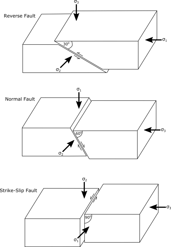
Figure 2. Simplified diagram of the three main tectonic environments and their associated faults as described by Anderson (1905).
Developing high-angle reverse faults
Because high-angle faults (~600) are extremely unfavourably orientated with respect to Anderson’s (1905) theory they are inferred to be reactivated pre-existing faults (Sibson, 1990a). Sibson (1990a) summarises four main methods for the formation of high-angle reverse faults through the reactivation or reorientation of existing structures. There are;
- Reactivation of normal faults (Fig. 3a). This occurs when a regional tectonic regime changes from a regime of extension containing high-angle normal faults to one of shortening. High-angle normal faults are then re-activated as high-angle reverse faults.
- Transpression across what was formerly a strike slip fault (Fig. 3b). Faults initially forming in a strike-slip regime transform into transpressional high-angle reverse faults with a change in tectonic processes.
- Re-orientation of thrust stacks (Fig. 3c). This occurs as a set of low-angle thrust faults become frictionally locked and rotate during shortening resulting in the rotation of the faults into a steeper orientation.
- Shortening across a mesh of conjugate faults (Fig. 3d). This occurs when formerly shallowly dipping shears become progressively steeper during shortening.
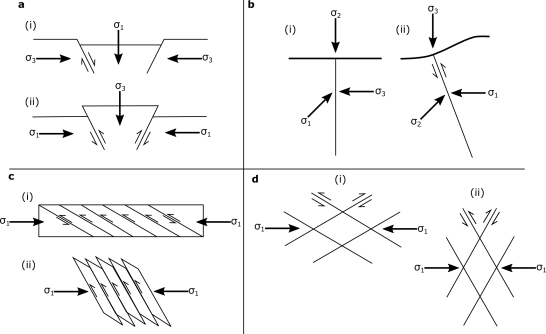
Figure 3. Diagram showing possible methods of developing high-angle unfavourably orientated reverse faults. a) Reactivation of a normal fault in a tectonic shortening regime. b) Reorientation of a strike-slip fault in a tectonic shortening regime. c) Rotation of a set of thrust stacks. d) Steepening of a set of conjugate shears during tectonic shortening. Figures modified from Sibson (1990a).
Reactivation of faults
The shear stress resolved along a pre-existing fault is governed by the following Coulomb equation:
τ = C + μs + (σn – Pf)
where τ = shear stress, C = cohesive strength of fault, μs = coefficient of static friction (often assumed 0.75), σn = normal stress, Pf = fluid pressure (Sibson, 1988). If the fault is assumed to have negligible cohesive strength (C), the equation changes to:
τ = μs + (σn – Pf)
For slip to occur along a fault the stresses promoting failure (τ, Pf) must overcome those resisting failure (C (if present), μs, σn). As a fault becomes more severely unfavourably oriented with respect to the prevailing stress field, the magnitude of the stresses needed to promote failure exponentially increase (Fig. 4) (Sibson, 1988).
Therefore in favourably oriented faults with low stress ratio’s (σ1/σ3), failure often occurs before fluid pressure builds up to the point in which it would induce slip. As a result, large volumes of fluid typically do not build up to be released during slip (Sibson, 1990a). Conversely, unfavourably oriented high-angle faults are the most likely faults to develop fault-valve behaviour (Sibson, 1990a). This is due to elevated fluid pressures building to the point of inducing failure, as the high σ1/σ3 prevents slip before this point. Failure is coupled with the release of fluid along the fault zone (Sibson, 1990a).
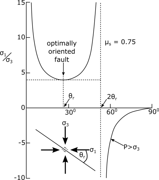
Figure 4. Figure showing the stress ratio σ1/σ3 with respect to the angle of reactivation (θr) that is required for failure along a cohesionless fault. As the fault become more unfavourably oriented (high θr) the stress ratio required for failure increases exponentially. Figure modified from Sibson (1985).
How is fluid pressure able to build up?
At shallow crustal levels fluid is under hydrostatic pressure (Fig. 5) as a result of interconnected brittle fractures and pore spaces linking to Earth’s surface. At depths approaching the brittle ductile transition pore spaces and fractures close. This creates an impermeable barrier and allows fluid to become pressurised to greater than hydrostatic levels (Fig. 5) (Sibson, 1988). This is called suprahyrostatic pressure, and with increasing pressure may approach the pressure of the surrounding rock at lithostatic pressure (Sibson, 1988). The source of fluid at this depth is inferred to be a result of dehydration of hydrous minerals under greenschist facies conditions in a tectonic shortening regime undergoing progressive metamorphism (Sibson, 2004). This fluid builds up below the impermeable barrier until it reaches pressures that promote failure (Sibson, 1988). For severely unfavourably oriented faults (faults > 530 to σ1), fluid pressure (Pf) must exceed the least principal compressive stress (σ3) for shear failure to occur (Sibson, 1990b). As the fault slips, pressurised fluid is able to escape upwards along the fault plane and associated fractures before hydrothermal precipitation of minerals reduces permeability and effectively seals the “fault-valve” (Sibson, 1988). Sibson (1992) inferres that the rebuilding of fluid pressure has as much, if not more influence than the reaccumulation of tectonic stresses in promoting the next failure and fault-valve event.

Figure 5. Figure showing how fluid pressure varies with depth. The fluid pressure increases to suprahyrostatic levels below the impermeable barrier. Figure modified from Sibson (1990a).
Vein formation
Many mesothermal gold-quartz deposits around the world have formed along high-angle reverse faults as a result of high fluid flux generated by fault-valve behaviour (Boullier and Robert, 1991; Gaboury and Daigneault, 2001; Sibson, 1988). One characteristic of these deposits are discontinuous and steeply dipping tabular-lenticular quartz veins oriented subparallel to the major shear (Fig. 6) (Faleiros et al., 2014; Robert and Brown, 1986; Sibson et al., 1988). The other major characteristic is the presence of subhorizontal extensional fracture veins, commonly referred to as flats, that extend for 10’s of meters away from the fault zone (Fig. 6) (Robert and Brown, 1986; Sibson, 1988). These mineralised vein systems have been recorded as far as 2 km down-dip of the high-angle reverse faults (Sibson, 1992).
The larger steeply dipping shear-parallel veins are thought to have formed during episodic slip and release of fluid along high-angle reverse faults from earthquakes (M 5.5-7) originating at the base of the seismogenic zone (Fig. 1).
The thinner subhorizontal flats are hydraulic extensional fractures that have opened vertically in an orientation perpendicular to the least principal stress (σ3) that is subvertically orientated. These fractures form when fluid pressure builds up to the point where it exceeds the tensile strength of the rock mass (T0) and the least principal stress (σ3) (Sibson, 2004). This is described by the equation:
Pf = σ3 + T0
However, for this hydraulic fracturing to occur the difference between the greatest and least principal stress must be less than four times the tensile strength of the rock. This is described by the equation:
(σ1 – σ3) < 4T0
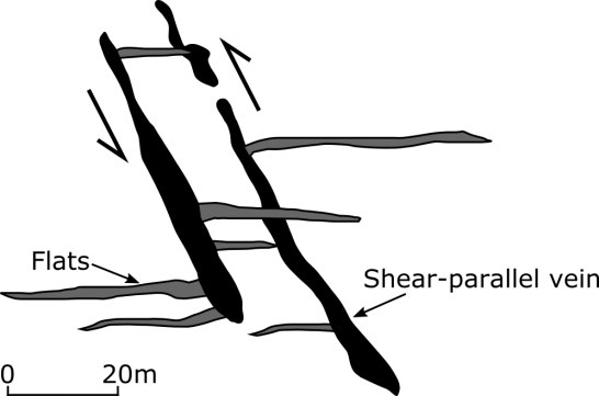
Figure 6. Schematic diagram of veins and flats displaying their cross-cutting relationships. Note how the veins are orientated parallel to the shear direction. Figure modified from Robert and Brown (1986) and Sibson (1992).
It is inferred that these flats form within the impermeable layer just before the main rupture event before the “fault-valve” opens releasing fluid vertically upwards and lowering the fluid pressure at depth (Sibson, 1992). Extensional veins or flats are not able to form in favourably oriented tectonic settings due to shear failure along existing fault planes occurring before fluid pressure builds to the point of failure (Kolb et al., 2004,).
Flats can be traced back to the steeply dipping veins subparallel to the shear zones. However, there is no consistent crosscutting relationship between either the flats or steep veins, which strongly suggests a cyclic contemporaneous formation through a fault-valve model (Sibson, 1988). Quartz from both steeply dipping shear-parallel quartz veins and flats show incremental fill textures, providing further evidence for cyclic and episodic precipitation (Sibson, 1988; Sibson 2004).
Precipitation and mineralisation
During episodic rupturing, fluids at the base of the seismogenic zone drop in pressure rapidly from suprahyrostatic to hydrostatic. The drop in fluid pressure has the result of lowering the solubility of quartz and metals (such as gold) in solution. It is this depressurization process of fluid that is inferred to be the primarly control on precipitation of quartz, gold and other associated minerals during fault-valve rupture events (Gaboury and Daigneault, 2000; Helgeson and Lichtner, 1987; Walther and Helgeson, 1977). The rapid drop in pressure also has the effect of causing boiling of the fluid, resulting in the separation of C02, which subsequently precipitates as carbonate in the high-angle fault zones (Sibson, 1988; Spooner et al., 1987). Fluid inclusion studies of vein quartz coupled with oxygen isotope studies off altered host rock indicate temperatures in the range of 270-450oC for vein formation and mineralisation (Kerrich, 1986; Robert and Kelly, 1987).
References
- Anderson, E. M. (1905). The dynamics of faulting. Transactions of the Edinburgh Geological Society, 8(3), 387-402.
- Faleiros, A. M., da Cruz Campanha, G. A., Faleiros, F. M., & da Silveira Bello, R. M. (2014). Fluid regimes, fault-valve behaviour and formation of gold-quartz veins—The Morro do Ouro mine, Ribeira Belt, Brazil. Ore Geology Reviews, 56, 442-456.
- Gaboury, D., & Daigneault, R. (2000). Flat vein formation in a transitional crustal setting by self-induced fluid pressure equilibrium—an example from the Geant Dormant gold mine, Canada. Ore Geology Reviews, 17(3), 155-178.
- Helgeson, H. C., & Lichtner, P. C. (1987). Fluid flow and mineral reactions at high temperatures and pressures. Journal of the Geological Society, 144(2), 313-326.
- Kerrich, R. (1986). Fluid infiltration into fault zones: chemical, isotopic, and mechanical effects. Pure and applied geophysics, 124(1-2), 225-268.
- Kolb, J., Rogers, A., Meyer, F. M., & Vennemann, T. W. (2004). Development of fluid conduits in the auriferous shear zones of the Hutti Gold Mine, India: evidence for spatially and temporally heterogeneous fluid flow. Tectonophysics, 378(1), 65-84.
- Norris, R. J., & Cooper, A. F. (1995). Origin of small-scale segmentation and transpressional thrusting along the Alpine fault, New Zealand. Geological Society of America Bulletin, 107(2), 231-240.
- Robert, F., & Brown, A. C. (1986). Archean gold-bearing quartz veins at the Sigma Mine, Abitibi greenstone belt, Quebec; Part I, Geologic relations and formation of the vein system. Economic Geology, 81(3), 578-592.
- Robert, F., & Kelly, W. C. (1987). Ore-forming fluids in Archean gold-bearing quartz veins at the Sigma Mine, Abitibi greenstone belt, Quebec, Canada. Economic Geology, 82(6), 1464-1482.
- Sibson, R. H. (1985). A note on fault reactivation. Journal of Structural Geology, 7(6), 751-754.
- Sibson, R. H., Robert, F., & Poulsen, K. H. (1988). High-angle reverse faults, fluid-pressure cycling, and mesothermal gold-quartz deposits. Geology, 16(6), 551-555.
- Sibson, R. H. (1990a). Conditions for fault-valve behaviour. Geological Society, London, Special Publications, 54(1), 15-28.
- Sibson, R. H. (1990b). Rupture nucleation on unfavourably oriented faults. Bulletin of the Seismological Society of America, 80(6A), 1580-1604.
- Sibson, R. H. (1992). Implications of fault-valve behaviour for rupture nucleation and recurrence. Tectonophysics, 211(1), 283-293.
- Spooner, E. T. C., Bray, C. J., Wood, P. C., Burrows, D. R., & Callan, N. J. (1987). Au-quartz vein and Cu-Au-Ag-Mo-anhydrite mineralization, Hollinger-McIntyre mines, Timmins, Ontario: δ 13 C values (McIntyre), fluid inclusion gas chemistry, pressure (depth) estimation and H 2 O-CO 2 phase separation as a precipitation and dilation mechanism. Ontario Geol Surv Misc Pap, 136, 35-56.
- Walther, J. V., & Helgeson, H. C. (1977). Calculation of the thermodynamic properties of aqueous silica and the solubility of quartz and its polymorphs at high pressures and temperatures. J. Sci, 277(10), 1315-1351.


You must be logged in to post a comment.